Quantcast
Channel: Sparky – Sparky's Answers
Viewing all 94 articles
Browse latest View live

2010 Buick Enclave CXL, A/C Does Not Cool Well

$
0
0

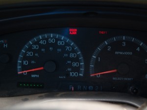
This 2010 Buick Enclave CXL came in with the complaint that the a/c is not as cold as it should be during the heat of the day. The problem is that with the ambient temperature being 98° F and the heat index at 112°F the best the vent temperature would drop to was the mid fifties. This was after ten minutes of driving at 50mph.  Granted that feels pretty good compared to the outside air, but it is not what should be expected from a late model GM vehicle.

This repair will generally apply to:

  • 2008-2015 Buick Enclave
  • 2009-2015 Chevrolet Traverse
  • 2007-2015 GMC Acadia
  • 2007-2010 Saturn Outlook

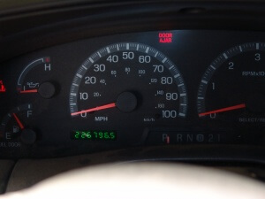
This Buick Enclave has automatic a/c controls as can be seen in the next picture. I noted that pressing the recirculation button made no audible change in the sound of the blower motor. Typically on any vehicle the sound of the blower motor should get significantly louder when the air flow is switched from fresh air to recirculation.

DSC01202

Checking the HVAC codes with my Tech 2 found a code B0228 symptom 61 , recirculation position feedback circuit actuator stuck.  I cleared the code and tried to command the actuator to move to no avail. The actuator was indeed stuck. A little trick to determine if there is a problem with the control head or the wiring is to disconnect the actuator and see if the code changes. If it does, it at least suggests that the control head is active to changes in the circuit beyond the code that had been previously stored. The wiring also has to be generally intact for the same reason. The code did change so I proceeded to replace the actuator.

DSC01200

The actuator is located behind and to the left of the glove box.

DSC01172

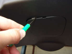
I started by removing the push pin clips that hold the lower hush panel to the underside of the dash. I used a small screwdriver blade to pry the center pin from the fastener.

DSC01199

Once the pin is pulled to this general position the whole fastener can be removed from the dash.

DSC01198

There are two push pin fasteners that hold this panel in place.

DSC01196

Opening the glove box reveals the stop pins on both sides of the glove box interior.

DSC01173

They rotate to the left and slide out of the glove box wall.

DSC01174

There is a rod on the right hand side in addition to the stop pin. I would recommend supporting the glove box door as you release the rod from the gear mechanism.

DSC01175

DSC01176

Once the glove box door has opened completely the right hand side can be lifted up and off of the hinge pins. It is a little snug and takes some effort to release it.

DSC01179

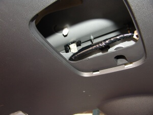
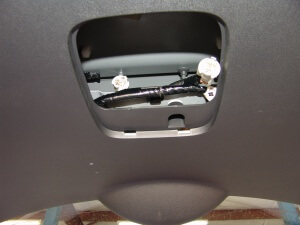
The recirculation or air inlet actuator is just to the left of the blower motor and what looks to be  slot for a cabin air filter. I could not get the right angle in order to see it in a picture.

DSC01192

It took both hands working through the openings to remove the three t20 torx bit screws that attach the acuator to the inlet door housing.

DSC01180

I used a two inch T20 bit with a 1/4″ ratcheting wrench to remove the screws.

DSC01181

Just in case you were wondering the actuator that you can see through the openings is the passenger side temperature door actuator. On this vehicle they are both the same part number.

DSC01194

There is also a wiring harness connector that has to be disconnected. I had to feel around for it and there was definitely no way to see it well enough to get a picture. Be careful when actually sliding the actuator off of the door shaft. There appears to be a white piece of plastic  that connects between the actuator and the actual door shaft. On this vehicle it appeared to slide out a little bit and gave the impression that it can come all of the way out and allow the door to drop down out of position. That would be real bad and would take hours to rectify. My advice is that it is better to be safe than sorry.

DSC01188

The old part on the right and the new part on the left. The old part had part numbers T3983001 and 010100841B. The new part had numbers T3983001 and 010141912A. You can purchase the part by clicking here.

DSC01183

When reinstalling the glove box the translucent part that I am holding has to be rotated down so that the rod will align with the slot.

DSC01195

After the actuator was installed and recalibrated the vent temperatures were now staying between 42° F and 46° F. Earlier I mentioned that there should be a substantial change in the fan noise as it is switched between fresh air and recirculation. On this vehicle the difference is there but it is minimal.

I of course used my scan tool to perform the recalibration but if you do not have one here is the procedure.

  • Begin with the ignition Off.
  • Remove the HVAC/ECAS 15 amp fuse for at least 10 seconds. The fuse is located in the interior fuse box.
  • Install the HVAC/ECAS Fuse.
  • Start the engine and immediately put your hands in your pockets.
  • Wait at least 40 seconds for the HVAC control module to self calibrate.  I recommend 50 -80 seconds.
  • Turn the ignition off for at least 10 seconds but no more than thirty seconds. Restart the engine and check HVAC operation.
  • If no problems were encountered by the HVAC module during this process the recalibration is complete.

2008 GMC Yukon, Reduced Power Mode, Code P0641 00 Stored

$
0
0

This 2008 GMC Yukon came in with the complaint of reduced power and the vehicle could not be driven over about 35 mph. There were a lot of codes stored but the only one of real relevance was Code P0641 Symptom 00, 5 volt reference circuit 1.  I looked at data under the TAC section of the PCM and found the circuit reading fluctuating between 0 and 5 volts. While the 5 volt reference circuit 2 was rock steady. This circuit provides 5 volt reference power to the MAP, FTP, ACP, APP2,  EOP and CMP sensors.

The wiring color codes are:

MAP, FTP, EOP  = Gray

ACRP = Gray/White

CMP = Dark Blue

APP2 = Tan

The 5 volt circuit is generated within the PCM and is bussed out through six different terminals.

PCM Connector X1 Terminal 33 = FTP

PCM Connector X1 Terminal 34 = ACRP

PCM Connector X1 Terminal 36 = APP2

PCM Connector X2 Terminal 41 = EOP

PCM Connector X2 Terminal 43 = MAP

PCM Connector X2 Terminal 44 = CMP

MAP (Manifold Absolute Pressure), FTP (Fuel Tank Pressure), EOP (Engine Oil Pressure), ACRP (Air Conditioning Refrigerant Pressure), CMP (Camshaft Position), APP2 (Accelerator Pedal Position 2)

This vehicle was a VIN “K”, indicating that it has four wheel drive. Since the FTP is at the rear of the vehicle and odd wiring issues commonly occur at the front drive shaft I decided to have a quick look. Pretty obvious that we a have a problem here.

DSC01230

Lifting the harness clearly shows that the harness had been rubbing on the front drive shaft enough that it had worn through the split loom covering.

DSC01231

DSC01232

I could see some signs of the internal wires being rubbed through the opening in the split loom.

DSC01233

Pulling the wires out and inspecting them revealed that the gray and the tan/black wires had been cut into by the front drive shaft.

DSC01234

DSC01235

DSC01236

I cut the wires right where they had been rubbed then installed heat shrink tubing and reconnected with a quality splice terminal.

DSC01237

Everything back together and secured. I positioned the harness in the clamp at the center of the next picture. I also wrapped that harness just below the clamp with a wire tie. This creates an obstruction on the outside of the harness that will prevent it from “walking up the clamp” from transmission movement.

DSC01238

Obviously I used a scan tool to monitor the voltage on the 5 volt reference 1 circuit and was able to locate this problem in a timely manner. One could also use a voltmeter and backprobe the respective wire at one of the easier to access sensors  or the PCM. Anything less than 5 volts would indicate a problem and a visual inspection of the harness would be needed. Particularly in the area noted above. If nothing was spotted the next step would be to disconnect all other sensors on this line until the voltage was restored. One at a time and rechecking voltage along the way. I have read reports of shorts with the CMP, EOP, FTP and ACRP sensors and their related wiring as also being causes of this code.

1990 Subaru Legacy L, Battery Goes Dead

$
0
0

This 1990 Subaru Legacy L came in with the complaint that the battery would go dead while the vehicle sat for a couple of days. This little Subaru had been to two other shops including a dealership without having the problem resolved. The battery had been replaced three times and the seat belt retractor motors had been disconnected.  I connected my multimeter amp leads in series between the battery negative post and the battery negative cable end. There was a nominal .30 amp draw even after letting the system sit for an hour. None of the test accessible fuses in the underhood fuse box showed any sign of a drain.

DSC01265

Moving to the dash fuse box under the driver’s side of the dash …

DSC01266

…I removed the cover to access the fuses for testing.

DSC01268

The 20 amp fuse in the dead center of the fuse box indicated  a current flow…

DSC01269

…of .80 millivolts.  Removing the 20 amp power door lock fuse also removed the .30 amp drain on the battery. Knowing that there was a problem in the power door lock system and that my testing up until this point had been done with the doors unlocked I decided to lock the doors and check the result. The drain went away. My thinking at this point was that there was a problem in a solid state module. The only issue with that train of thought was that according to the wiring diagram there are only four actuators and one switch. No modules in the system.  Then my thought process changed to bent linkage inside the driver’s door.

DSC01270

To access the linkage and the single switch, the door panel has to be removed. There are three phillips headed screws at the lower front corner of the door panel that have to be removed.

DSC01250

The interior door handle trim panel is held in place by three locking tabs. One under the handle as shown below and one above the handle in the same general area.

DSC01253

Then the trim panel needs to be pushed slightly towards the front of the door to release the third clip.

DSC01254

Then the cover shown below has to be removed to access the screw behind it.

DSC01251

DSC01256

There may or may not be a piece of foam that has to be removed in order to access yet another phillips headed screw.

DSC01252

DSC01255

This triangular panel needs to be removed either grabbing or prying at the upper end and pulling it loose from the door.

DSC01257

DSC01258

Then the door panel can be grabbed and the lower front edge and pulled loose from the door. Working around the edge to loosen all of the push pin clips. After the edges are loose the door panel can be lifted up and then off of the door.  Looking down at the inside of the door panel the power window switch assembly can be disconnected.

DSC01259

This door panel has been off several times and there was sticky black adhesive all over the place. I had to carefully pull the vapor barrier loose at the lower rear corner, roll it forward and secure it in place with tape to keep the sticky adhesive from going everywhere.

DSC01260

After following the wiring harness down and reaching inside the door I was able to disconnect the power door lock switch. I did remove the switch and door latch assembly thinking that I would find some sort of damage that was causing the battery drain issue but after careful examination I determined that the linkage and the switch were not the problem. By the way the drain was also gone with the switch disconnected.

DSC01261

Instead I turned my attention to testing the circuits going into the power door lock switch. The red wire has power at all times and is supplied by the power door lock fuse. There is supposed to be a constant ground on the red/yellow wire. All other wires are supposed to read open. Meaning no continuity to ground or power. I found a ground circuit on the black wire. Looking at the wiring diagram I realized that the black wire attaches to each of the door lock actuators. Internally each actuator has a blocking diode built in to the circuitry. I removed all of the door panels and disconnected all three of the door lock actuators. The driver’s door on this model does not have an actuator. It relies on the movement of either the key or the interior door lock handle to actually lock and unlock the door with a mechanical linkage.  My drain was still there and it had me scratching my head until the light bulb went off and I remembered that the tailgate also has a lock actuator. After disconnecting that actuator the drain was gone.

DSC01262

I called the dealership to order a new actuator and found out that it was only supplied as the latch and actuator assembly. However it was no longer available. I searched high and low and finally found a new actuator by itself as a Airtex/Wells part number DLA598. Do not confuse it with a SMP / Standard Motor Products part number DLA598. The SMP part fits a Dodge application and not a Subaru.  It is listed as a right front door lock actuator for a USA model Legacy L. I think I may have bought the very last one in existence. As a final note I took the old actuator apart in order to replace what I thought would be a faulty diode. The diode tested as being good. I also found a capacitor also installed in the actuator. To get the actuator apart I wound up having to damage the electrical socket portion since it was designed to be assembled one time and not to be taken apart. If I had not been able to find a replacement the repair of the battery drain would have been to simply disconnect the tailgate door lock actuator.

2006 Honda Accord, Passenger Power Windows Do Not Work

$
0
0

This 2006 Honda Accord came in with the complaint that all three passenger power windows did not work. The driver’s window worked fine. This is a relatively common issue and the vast majority of the time the driver’s power window switch is the culprit but I thought that I would show some basic tests and suggest a method of overcoming without having to purchase a $200 USD switch assembly. Start by locating the interior fuse box and testing for power on the passenger power window fuses with the ignition on and the lockout switch off, red line showing. They are fuses 24,25 & 26.

DSC01349

The first three yellow 20 amp fuses in the upper row. Remember the ignition needs to be on and the lock out switch turned off (red line showing). I did not have power to any of those fuses. Fuse 27 was powered and good but I already knew that since the driver’s power window works. I should also mention during all of this you will notice that there is a clicking noise that comes from each of the passenger doors when the passenger switches are operated on the driver’s door.

DSC01350

Time to test the circuits at the driver’s power window switch. I have found that this is the best place to start lifting the panel from. Doing so will allow the inner side of the switch to come up and then the rest will release without any trouble. Trying to lift on the outer edge first is more difficult and could mar the plastic with pry marks.

DSC01348

Like I stated earlier the rest of the switch retainer clips release pretty easily one the inner edge is lifted.

DSC01347

Now on to testing. Two things need to be tested. There needs to be power in the white green wire and both black wires need to have a constant ground.

DSC01344

Luckily this was s straight forward test as shown with the meter reading below. For this test the lockout switch needs to be on meaning that the red line is not visible. If I would not have had a clear reading I would have had to of used other tests to chassis ground and battery voltage in order to determine if there was a broken wire or other issue somewhere.

DSC01342

The voltage stayed the same….

DSC01346

…. regardless of the lockout switch position.

DSC01345

This is the expected and real voltage with the new switch assembly installed ….

DSC01343

…. with the lockout switch off. The terms on and off are strange in reference to this switch. As far as user function is concerned the switch is considered on or lock out function activated when the button is pushed in and the red line is not showing. It is considered off or the function unlocked when the button is in the out position with the red line showing.

DSC01345

Electrically it is just the opposite. Remember the white/green wire that had to be tested for voltage? That voltage is actually bleed through voltage from the passenger window relay’s internal coil. The switch grounds that wire and turns the relay on by applying a ground to the circuit. That is why the voltage drops. So turning the switch off functionally is electrically turning the switch on to complete the relay circuit. To extend the life of the switch assembly it should be left in the on position without the red line showing. This keeps the load off of the relay and the driver’s master switches internal circuitry.

Now what to do if you need the passenger power windows to function but the switch is faulty and you do not have the funds for a new one.  Remember the white/green wire. You can apply a temporary ground to that wire, turn the ignition on and operate the windows. You cannot leave the added ground in place though as it will keep the relay energized even with the key off and the battery will go dead. I do recommend removing the wire from the switch harness connector before grounding the white/green wire. If want want a slightly more convenient alternative to a new switch you can add a momentary on off switch between the white/green wire and chassis ground. This will result in having to hold the momentary switch in the on position and operate the desired window switch at the same time. Releasing the momentary switch will deactivate the circuit and lockout the passenger windows.

DSC01344

My choice is to always install a new factory master window switch when there is a failure but I do understand that circumstances sometimes dictate another path. If you replace the power window switch you will need to do some minor relearn and programming procedures.

Remote Programming:

First of all the vehicle remotes will need to be programmed to the vehicle once the power window switch assembly has been replaced.  To do so all you will need to sit in the driver’s seat with the hood, trunk and all doors closed.

Turn the ignition on, position (II).

Within 1 t0 4 seconds press remote lock or unlock button with the remote pointed towards the power window switch assembly. If only one remote/key assembly is available it will work from the ignition switch location as long as the battery is strong.

Within 1 to 4 seconds turn the ignition off.

Repeat this process for a total of four times making sure to never let more than 4 seconds transpire between actions. At the end of the fourth cycle you should hear the door locks activate on their own. As soon as the movement is heard push the lock or unlock button one more time. This is when the actual remote transmitter code is stored. The rest of the actions you took are merely getting the system into learn mode. If you have more remotes that you want to program to the vehicle simply aim them at the power window switch and press the lock or unlock button once. The door locks should cycle indicating the remote was learned. This must be done within 10 seconds of the very first remote being learned. A total of three remotes can be learned to a vehicle.

Turn the key off and remove it from the ignition. Test all remotes to confirm their operation.

I recommend choosing either the lock or unlock button at the beginning and using that same button function the whole way through the programming procedure.

Relearn Auto Window Limit Functions:

The Honda method without a scan tool is as follows:

1. Begin with sitting in the driver’s seat with all doors closed.

2. Turn the ignition switch ON (position II).

3. Move the driver’s window all the way down by using the driver’s window DOWN switch.

4. Open the driver’s door.

NOTE: step 5-8 must be done within 5 seconds of each other.

5. Turn the ignition switch OFF.

6. Push and hold the driver’s window DOWN switch.

7. Turn the ignition switch ON (position II).

8. Release the driver’s window DOWN switch.

9. Repeat step 5-8 three more times. These actions are performed to clear out the old stored memory

10. Wait 1 second.

11.Confirm that AUTO UP and AUTO DOWN do not work. If AUTO UP and DOWN work, go back to step 1. Now the system is ready to learn the new positions.

12.Move the driver’s window all the way down by holding the driver’s window DOWN switch to the AUTO DOWN position.

13.Pull up and hold the driver’s window UP switch to the AUTO UP position until the window reaches the fully closed position, then continue to hold the switch for 1 second.

14.Confirm that the power window master switch is reset by using the driver’s window AUTO UP and DOWN function.

If the window still does not work in AUTO, repeat the procedure several times, paying close attention to the 5 second time limit between steps. If it still does not work, you will need to diagnose the system using a scan tool then relearn the positions.

Auto Window Universal Relearn Procedure:

The auto window function  will also need to be relearned. This can be done by turning the ignition on and pushing the down button and holding it down for 2-3 seconds after the window bottoms out. Then hold the switch in the up position until the window  tops out and stops moving. Again hold the switch in that position for an additional 2-3 seconds.  Switch the ignition off and back on. Test the window for proper auto down and auto up functions. This method works on many vehicles.

2006 Hyundia Tucson, Park Lights Stay On

$
0
0

This 2006 Hyundai Tucson came in with complaint that the park/tail lights would not turn off. As you can see below the park lights are on….

DSC01385

…. and the light switch is off.

DSC01384

Testing begins at the interior fuse box at the driver’s door opening. I am pointing to the right hand tail light fuse. Oddly enough the left hand tail light fuse is just to the right of the right hand fuse. I know it is a very small thing but wouldn’t you think that the left hand tail light fuse would be to the left of the right hand tail light fuse. But I digress.

DSC01383

I used a terminal that is the same size as a mini fuse blade terminal. Checking for power on the left side of both of the fuse slots indicated that power was being sent out from the tail light relay but remember the switch is off and the relay should be deactivated.

DSC01380

DSC01379

I also checked for power on the right terminal at each fuse slot. There was no power which was good thing. If there had been power on those two terminals it would have meant that the tail lights were on with the fuses removed and that they were being powered by an alternate power source.

DSC01381

DSC01382

A little bit of research showed that the tail light relay is built into the interior fuse box. There are a few screws that hold the under dash trim panel in place. All of the screws have phillip’s heads. One at each lower corner of the panel.

DSC01407

Two just to the rear of the hood release handle. The panel just unsnaps from the dash once the screws are removed. There is also a metal panel under this plastic panel. All of those fasteners have 10 mm heads. The data link connector also has to be removed from the panel by squeezing in the latches at either end of the connector.

DSC01408

There are three fasteners that hold the fuse block to the dash. Almost impossible to see so there are no pictures. Although all have 10 mm heads, two are bolts and one is a nut. The lower bolt at the forward edge is easy to get to. The upper bolt along the forward edge and the nut on the inside edge above the harness connectors are difficult to see and needed a swivel socket and long extension to remove them.

DSC01406

Once the fuse block is dropped down it is just a matter of disconnecting the harness connectors. There are also three harnesses that are secured to a metal strap at the lower forward edge of the fuse block. You should have probably disconnected the battery before getting to this point. I was scheduled to install a new fuse block that was ordered from a local dealer the day before. The customer and myself were both quite pleased when we were told the fuse box price was about $78 USD plus $8 USD for expedited shipping. Low and behold it came in and was the wrong part. They had ordered and sent the underhood fuse block instead. A few phone calls and a fax later and the proper part was identified but the price had changed to $358 USD and not in stock. Had to be ordered again.  Mind you that it is Friday afternoon on Labor Day weekend. Time to switch plans.

DSC01405

If at all possible I would like to fix the relay inside the fuse block. I started by removing all of the fuses from the assembly. Then I went around the outside edge of the fuse block assembly and pried the sides apart to release the latches.

DSC01403

A gentle wiggle and the cover was out of the way. The green circuit board assembly took a little more wiggling and prying to remove it from the plastic case.

DSC01404

I did not know which relay was at fault and it would be very dangerous to try and reconnect everything with the circuit board outside of the plastic case so I decided to remove all of the relay covers. The larger relay covers were not too hard to remove. I slid a curved pick under either side and flipped them up with little difficulty.

DSC01397

Of course I found no problems with the contacts on either of the two larger relays.

DSC01398

That meant removing the cover from the smallest relay. I had to pry along the edges of that cover in the same manner but in the end I had to break the cover in order to remove it.

DSC01399

I inspected the contacts of the smaller relay with a magnifying glass and could see the build up of material on one of the contacts. What happens on any relay is that when the contacts are move to the closed position there is an arc. When the arc occurs metal is displaced from one contact and usually transfers to the opposing contact. This happens many time in the life of the relay. A hill of metal fragments build on one contact. The other contact that is losing metal has a valley formed in the contact face. After enough build up is formed the two surfaces mechanically stick together. I am pointing to the contact are of the relay below.

DSC01395

I used a utility razor blade to shave the hill off of one contact and therefore removed the mechanical locking forces that were causing the contacts to stick together. It was that mechanical force that was keeping the park/tail lights on. I used super glue to add extra support to the relay covers that had been removed earlier.

DSC01396

In the end this Labor Day Weekend was going to be a little bit better for both me and my customer. They had their vehicle and my head hurt a little less.

2004 Chevrolet Tahoe, Compressor Will Not Turn On

$
0
0

This 2004 Chevrolet Tahoe came in with the complaint that the a/c was not cold due to the compressor not coming on. Whenever the a/c was turned on the snowflake on the digital display would flash. This Tahoe has auto a/c controls. I checked codes with my Tech 2 scan tool and there was a code B0159 stored for an issue with the ambient temperature sensor. I looked at system data stream and could see that both the raw and filtered outside air temperature readings were at -40 °F and that a/c permission was not granted. Time to go find the outside air temperature (OAT) sensor. The sensor is located behind the passenger side daytime running lamp socket.

The first step is to rotate and pull the pins for the passenger headlight assembly.

DSC01394

Then remove the headlight assembly. The light assembly does not need to be electrically disconnected and fully removed from the vehicle unless you just choose to.

DSC01393

With the headlight assembly positioned out of the way the locking tab for the DRL assembly can be depressed…

DSC01392

…. and the assembly pulled loose from the vehicle.

DSC01391

The OAT position can be seen in the next picture. It is merely snapped into a retaining hole just to the inside of the DRL socket.

DSC01388

The OAT and it’s harness assembly. Note that it is a new sensor that I had just installed.

DSC01387

The old/original OAT in my hand and the new one hanging below.

DSC01386

The new sensor installed.

DSC01390

Testing the sensor wiring is as follows.

The light green/black wire should have a nominal 5 volt signal which is supplied from the HVAC control head assembly on terminal B.

The brown wire is a system low reference signal (return ground) and is supplied from the HVAC control head assembly on terminal K.

The higher the resistance the colder the reading. An open connection between the two circuits will yield a -40°F reading on the scan tool.

The lower the resistance the higher the reading. A shorted connection between the two circuits will yield a 100°F + reading. I did not take an actual reading during this test as it was not relevant to the current issue.

The data will be reported on the scan tool as Outside Air Temperature Raw.

After replacing the sensor the data reading changed to actual ambient temperature which was 95°F. There was also about 90% relative humidity. Those conditions coupled with the pressure to get the job done are why I do not have some pictures. In particular scan tool screen shots.

There will be another data line in the scan tool data listed as Outside Air Temperature Filtered. That data line appears to refer to the sensor used for the thermometer built into the rear view mirror. I also had a reading of -40°F on this circuit as well. The displayed temperature in the rear view mirror fluctuated between -40°F and -26°F. The compressor was still not coming on.

Time to move on to the other OAT sensor. It is located in front of the condenser assembly and is accessed by removing the cover over the top of the radiator and condenser area. That panel is held in place by push pin retainers. The center pin has to be lifted most or all of the way out before the main pin can be pulled free.

DSC01402

With the cover removed and looking down on the driver’s side between the condenser and the grill the OAT sensor can be seen.

DSC01401

DSC01400

Now you would think that by simply changing the faulty sensor everything would go back to work and both the raw and filtered data would be correct with actual conditions. Not so. I suspect that they would have adjusted if I would have had test driven the vehicle but since I was still working on the refrigerant system that was not going to happen anytime soon. Under “Special Functions” there is a command function to perform and “Instant Update” for the OAT. Performing that task updated the data and the compressor came on as it should have. There was no code for the -40°F reading of the Filtered OAT. I had tried using that function before to try and rectify the condition with the faulty sensor and it did not work. It only worked with a good sensor installed. Well kind of. While I was waiting on a new sensor I connected my decade resistance box to the circuits and played around with the values. I knew the signal that was being generated by the suspected faulty sensor was about 1.45 volts and that correlated with a -40°F to -27°F thermometer reading. I found that a .4 to .6 volt reading resulted in a 95°F reading on the thermometer. Disconnecting the sensor from the harness resulted in a reading of OC. Jumping the terminals together with a jumper wire resulted in a reading of SC.  My assumption is that OC means open circuit and SC means shorted circuit. By the way, the above tests that resulted in the OC and SC readings was enough to tell me that the sensor was the problem.

2011 Nissan Rogue, Changing The License Plate Bulbs

$
0
0

This 2011 Nissan Rogue came in with one of the license plate or tag light bulbs blown. Replacing the bulbs is actually quite easy. Lift the tailgate and look at the interior panel. There is a rectangular cover with a screwdriver slot at one end. I found it difficult to remove the cover by prying in this area.

DSC01411

Instead I went to either side of it and slid my pocket screwdriver in and pried and twisted it a little. Then I moved to the other side in the same general location.

DSC01412

Looking up into the opening the tag light bulb sockets can be seen.

DSC01410

I twisted them both out and replaced both bulbs even though only one was acting up. They have both been on the same amount of time and lived through the same vibrations. So the other one will likely fail soon.

DSC01409

Both tag light bulbs working.

DSC01413_blur

I should note that pulling the tailgate back down slightly to get a better angel made the job a little more comfortable.

2008 GMC Sierra Denali, Multiple Electrical Problems

$
0
0

This 2008 GMC Sierra Denali came in with multiple electrical complaints. The blower did not work. The left side stoplight, all left side turn signals, the right side mirror turn indicator. All of the power windows except for the right rear window did not work. There were a multitude of codes scattered through various modules. Most were stored in the DDM and the PDM. I did some testing of various circuits and decided there must be a problem with some of the major power supply fuses.

The 40 amp Blower fuse at position #70 was blown.

DSC01428

The 60 amp LBEC2 fuse at position #72 was also blown.

DSC01429

The underhood fuse box legend

DSC01431

Some of the testing that lead me to the underhood fuse box was the fact that all of the fuses in the row I am pointing to with my test light were unpowered even with the ignition on.

DSC01432

The driver’s side fuse box legend.

DSC01441

It took a little bit of looking around but I found where the wires were shorting out above the parking brake assembly.

DSC01433

A little bit better view of the shorted wiring harness.

DSC01434

DSC01435

A clear view of the shorted out wires with the harness tape pulled back.

DSC01436

In the end I had to cut and splice one of the wires back together. The other two only had the insulation slightly damaged so I wrapped them with live rubber tape. Wrapped that with regular electrical tape. Wrapped the wiring harness back up where the tape had previously been removed then covered all of that with some large split loom. I also reformed the harness to stay away from the parking brake assembly.

DSC01464

I found it easier to work by removing the under dash panel on the driver’s side of the truck. There is a 10 mm headed bolt that holds the parking brake release handle in place.

DSC01440

Once the bolt was removed the handle assembly had to be slid towards the firewall in order to disengage the hooks.

DSC01439

There are two phillip’s headed screws along the lower edge of the panel that have to be removed. One at either corner.

DSC01438

Then the panel can be pulled from the dash by pulling it towards the seat. That will disengage the retaining clips.

DSC01437


2011 Nissan Rogue, Changing The Front Turn Signal Bulbs

$
0
0

This 2011 Nissan Rogue came in with the complaint that the right turn signal would flash very quickly when turned on. I did a quick visual inspection and found that the right front turn signal bulb was flashing on the wrong element. It was evident to me as it was not as bright as it should have been and as compared to the other front turn signal. both rear bulbs flashed equally as bright. Also looking closely at the bulb I could see that the taller element was the one that was lighting up and not the shorter/brighter element. This is generally caused by a poor ground to the bulb. The element cannot utilize the main bulb ground so it uses a back fed ground from the park light element.

The front turn signal/park light socket is shown in the following picture. It is the recessed white part at the very center of the picture.

DSC01415

It can be removed without removing the headlight assembly. It twists and pulls out of the lamps assembly.

DSC01414

Once it was out I realized that the bulb had been recently changed. I checked and the bulb itself was okay.

DSC01416

However removing the bulb revealed the problem that I was looking for. The side ground terminal was collapsed and not providing an adequate ground to the light bulb. The power contact terminals also seemed to be collapsed. There was absolutely no evidence of heat build up so the diagnosis was that of possibly aggressive bulb replacement coupled with a weak design had collapsed the terminals. I used a small pocket screwdriver to bend the tabs back out and restore the spring tension to the terminal contact points.

DSC01417

If there had been any evidence of heat build up or if the terminals had seemed excessively weak I would have had to order new sockets.

DSC01418

Now the light was working as designed. While I had to hood up I repeated the process on the driver’s side front turn/park light socket.

DSC01419

Changing the Crank Sensor ,Code P0335, On An H2 Hummer

$
0
0

In case you were ever wondering how to change a crank sensor on an H2 Hummer all I can say is you need to be about six feet tall and be able to get into the following positions.

DSC00877


Much shorter and you will not have the arm length needed. Much taller and I am not sure if you can fold up enough to fit.

DSC00878


Although I may appear to be asleep in the next picture I am not. I have found over the years that when I cannot see what I am doing it is actually easier to close my eyes and only feel what I am doing.

DSC00879

2008 Chevrolet Cobalt, Blower Inop

$
0
0

This 2008 Chevrolet Cobalt came in with the complaint that the blower motor did not work at all. It had been working intermittently. Looking under the passenger side of the dash behind the glove box  I found the two wire harness connector at the blower motor.

The brown wire should have had battery power on it with the ignition on. It had no voltage present.

The orange wire should have had a full switched ground signal on it with the blower switch at the high position. The amount of battery ground will change if the blower switch is at any of the lower speeds. It will go open if the blower switch is in the off position. The ground circuit tested okay. The ignition does not have to be on to check the ground circuit.

DSC01845

The next logical place to test was at the blower relay. It is listed on the fuse block legend as the HVAC relay at position #30. I did a quick test by feeling the relay and switching the ignition to see if the relay clicked. It did and that proved that the circuits to the terminals 85 and 86  of the relay were working. Next I confirmed that there was battery power at terminal 30 at the relay socket. It was present. If it had not been present I would have proceeded to the BCM 3 fuse in the underhood fuse block for further testing.  I then used a fused jumper wire and connected terminals 30 and 87 together in the relay socket.

DSC01856

DSC01854

This should have sent power directly to the blower motor but the motor still did not work. Testing again at the blower motor found that power was still missing on the brown wire.

DSC01845

I had already consulted the wiring diagrams for this system before testing so I knew that there was an in line harness connector (X210) at the far passenger side of the dash. To locate it I removed the glove box assembly starting with the cable retainer at the right side of the glove box.

DSC01861

DSC01862

To do this the outer edge of the black clip has to be lifted slightly so the the clip can be slid towards the front of the glove box and removed.

DSC01864

The stop peg on the left side has to be pushed inward to release the left side of the glove box.

DSC01863

When the glove box swings fully down it exposes the hinge pins. The right one has to be lifted slightly and then that corner of the glove box has to be pulled towards the seat. Then the center one needs to be dropped down. Finally the left one has to be lifted up and the glove box again pulled towards the seat.

DSC01860

I had found this connector without pulling the glove box out but I found it easier to see and work with the glove box removed. A close look at the next picture reveals darkening of the brown wire insulation near the connector. I tried to pull the connector apart but it was melted firmly together.

DSC01846

I simply cut the in line harness connector out and spliced the wires back together. I made sure that the ignition was off so that I would not blow the fuse that powers the brown wire.

DSC01847

DSC01852

Later I used pliers and a screwdriver to separate the old connector and exposed the burnt terminal.

DSC01866

After repairing the faulty wiring connection I used a headlight bulb and harness connector with the appropriate terminals installed to check power and ground at the blower motor connector. I already knew that the blower motor was now working correctly but I just wanted to show another test method for those that may be interested. Caution should be used in doing this test as the bulb can get very hot. Safety glasses are also recommended as the glass portion of the bulb can shatter. It is safer to do this test with a sealed beam headlight.

The next picture shows the light burning dimly  with the lowest blower speed selected.

DSC01848

Blower speed 2 selected.

DSC01849

Blower speed 3 selected.

DSC01850

Blower switch set to high, speed 4.

DSC01851

The varying light intensity is caused by the ground supply voltage being reduced through the blower resistor. High speed bypasses the blower speed resistor on the orange wire.

DSC01853

I prefer using a headlight style bulb as opposed to a regular test light as it requires more current to operate it. The same test with a regular test light will not show as distinct a difference between the blower speeds.

An additional note to this repair was that after the system was back working I found that the blower speed would change if the connector to the blower motor was wiggled around. I disassembled the connector and re bent the terminals spring tab in order to tighten its connection to the mating blower motor terminal.

2008 Buick Enclave Replacing The Alternator

$
0
0

This 2008 Buick Enclave CXL came in with the complaint that the battery would go dead while driving. The battery light was on and there was a message on the dash to service the charging system. Something else that I noticed but cannot duplicate here is that there was a steady moan from the engine area.  This article is more about how to replace the alternator and less about diagnosis. The battery should be disconnected. It is located under the floor board behind the passenger front seat.

The first step in removing the old alternator is to remove the oil filler cap.

DSC09106

Doing so allows the top engine cover panel to be removed.

DSC09105

After the oil filler cap is removed the cover will lift straight up and off of the engine. Notice the two silver studs with ball tops at the rear of the engine. These match up to sockets in the cover.

DSC09104

The coolant overflow tank is the next part to be removed.  There is a hose attached to the tank that is easier to remove before the tank is unbolted.

DSC09100

Now the two 10 mm headed bolts that hold the tank in place are removed.

DSC09098

One more bolt holding the a/c high pressure line in place. The a/c line and a power steering hose will need to be moved around slightly while working the alternator around the engine compartment.

DSC09099

The tank can be positioned out of the way in several different directions depending on the area of access needed at the time.

DSC09097

Following the a/c liquid line around to the front of the engine you will find a 10 mm nut holding the clamp down.

DSC09096

The belt tensioner assembly is accessed from under the vehicle. I used a 1/2″ drive breaker bar to move the tensioner and then removed the belt from the alternator.

DSC09095

While in the same area the bolt that holds the back idler pulley in place also needs to be removed. That bolt doubles as an attaching bolt for the alternator.

DSC09094

It can be accessed from the bottom or the top of the vehicle. The bolt has a 15 mm hex head.

DSC09090

This is a better view of the pulley, bolt and alternator as they are assembled in the vehicle.

DSC09087

The bolt and pulley will need to be moved to the most forward position possible in order to remove the alternator.

DSC09088

After the alternator is free enough for it to rotate up, the pulley and bolt should be removed. This will make moving the alternator around much easier. It is a must to remember to reinstall the pulley and bolt back into the alternator housing before securing the alternator to the engine. This pulley and bolt cannot be removed from the alternator while it is still bolted in place and by the same token it cannot be installed if the alternator is already secured to the engine. 

DSC09089

Moving to the mounting studs and nuts that hold the bulk of the alternator to the engine. The GM service information states to remove the bolts but this vehicle uses studs instead. So after removing the two 15 mm nuts and the hose bracket from the studs, the studs themselves will need to be removed.

DSC09084

A 7 mm socket is needed. There are quite a few threads so it takes a lot of turning to remove the studs.

DSC09085

This is how it looks in the engine compartment. I will tell you that it is easier removing the studs than it was to re install them. I had to use my left hand under the front of the alternator to support it while I re installed the studs with my right hand. You may notice the alternator output stud slightly right of center in the next picture. The attaching nut has a 13 mm hex. I had already removed it and moved the cable out of the way earlier. Same goes for unplugging the alternator harness connector.

DSC09092

Now the trick for easy removal out of the engine compartment. Under the vehicle at the front the of the wheel well there is a phillips headed screw that needs to be removed.

DSC09103

There are several more along the front half of the inner fender. It is easier to work with the wheels turned to the right.

DSC09101

There are several push pin style plastic retainers that also need to be removed. After all of the fasteners are removed the front portion of the wheel liner will pull down and out of the wheel well.

DSC09102

The alternator can then be maneuvered out through the passenger wheel well opening. It may seem like a pain to take the alternator out this way but it is far easier than doing it by the factory manual. It states to drain the coolant, remove the upper radiator hose, remove the front engine mount and then the engine mount bracket before unbolting the alternator.

DSC09083

Hope this helps.

2009 Lexus ES350 Evaporator Core Replacement

$
0
0

These are just a few pictures that show just how much has to be removed in order to replace a leaking evaporator core in a 2009 Lexus ES350. This was my first time doing this job on this year,make and model of vehicle so it was a bit of a learning experience. I don’t do a detailed breakdown of such an extensive job until I have done it at least twice. The next picture shows the white HVAC box just before it comes out of the vehicle. The most difficult and time consuming part of this repair was removing and installing the major cross bar that supports the HVAC case and the rest of the dash assembly. The wiring harness is wrapped around the bar and it took two of use to snake it out of the car and back in. In retrospect I should have went ahead and removed the seats, shifter assembly, flipped the carpet further back and pulled all of the harness above the bar to make the job easier. I possibly would not have needed help removing the bar if I had done that.  I will have to time it out in order to decide which is the more cost effective way.


DSC01378


The hole in the firewall slightly high and to the right of center is where expansion valve protrudes through into the engine compartment so that the refrigerant lines can be attached. The opening above the gas pedal area is where the heater core lines pass through the firewall.

DSC01377

DSC01376


It took me between 10 and 12 hours to complete the job this time and I learned a few things along the way.

DSC01375


The next time I should have it down to between 6 and 8 hours because I will take pictures along the way. Experience tells me that after one or two times of doing this job it can most likely be done in 4 to 5 hours of steady wrenching.

Britney & The Mazda MX6, Part 3 Conclusion

$
0
0

I had actually about forgotten about this story or at least, it has not been at the top of the list of tasks to complete. In one of my recent email conversations with Katie on our web development team, she stated that while looking through the site in preparations for a new project that she ran across these articles. She wanted to know how it turned out. I decided to take the time to write the conclusion to the story. The names used are not the real names of the people involved and I am sad to say I cannot remember the name of the aid agency that was involved in this story. I just realized it has been slightly over six years since this all happened.

To read the first two parts of this story please visit the following articles.

Britney & The Mazda MX6, Part One

Britney & The Mazda MX6, Part Two


Britney came by on Monday morning and said she was sorry for the confusion and did not know exactly what happened. I told her that I had a pretty good idea what was going on and that I would need to speak with her contact at the aid agency that had been helping her. She stated that she would get her on the phone.  I replied that I was too busy to talk at that moment and that I would need to call the agency as soon as I was free. To my surprise she actually gave me the phone number and the name of the contact person at the agency, Jennifer.  I looked the number up on the internet and found it indeed belonged to a legitimate organization. I had expected to call one of Britney’s friends that would be posing as “Jennifer”.

About mid morning when the shop settled down I called Jennifer and asked if she knew Britney and the situation with the Mazda. She stated that they had been helping her get her life back together since her child had passed away (a very sad bit of truth in this whole story). She was aware that there was a broken down Mazda that Britney needed to get running for a new job and that they would be paying for the repairs.  For a split second I debated whether or not to inform Jennifer of Britney’s deceptions as she seemed very caring and deeply involved in Britney’s plight. Whether it is a blessing or a curse I have always been compelled to do the correct thing in life and I told her the whole sorted story as I knew it. I presented it as kindly as I could. She was not surprised and informed me that she had personally taken an interest in Britney and was well aware of her tendencies to manipulate people and situations to her own selfish ends. It was among many things she had been trying to help her with. She further stated that she would be paying the bill on the car and that she would make Britney bring the check to me and apologize in person for the whole situation. It did not seem right to me for Jennifer and the aid agency to do this for Britney since in my opinion Britney had been scamming them for quite a while. What the heck, I know cars not people.

About an hour and a half later Britney’s friends from the weekend arrived at the shop. I explained the situation to them and that as far as I knew Britney would be arriving shortly with the payment for the repair. They stated that was okay but Britney no longer owns the Mazda. I asked for proof of that statement and they opened a folder and presented a nice crisp Vehicle Title. They also pulled out a driver’s license to prove their identification. I asked how they got the title and they explained that Britney had signed the bill of sale on the old title when the $100 deposit was given for the Mazda. They did not want to lose their $100 so when they had the chance, they lifted the title from Britney without her knowing it and transferred the title, first thing Monday morning.  I came right out and asked if they intended to still pay her for the car or if they were simply going to “steal” it.  They said no they had the money and fully intended to pay the balance for the car. I asked to see the money and they produced it. I told them I had to call Jennifer at the aid agency to see how this could all be worked out. Between the parking lot and the office the idea hit me. How about Britney’s friends paying me for the repair work and paying the aid agency for the balance on the transaction. From there Jennifer could then do what she wanted to help Britney and Britney would be taught the lesson that maybe she is not quite as smart and crafty as she thinks she is. To my surprise Jennifer agreed with my scenario and we put the plan in action.

Back to the parking lot to talk with Britney’s friends! They agreed. I brought them into the office and called Jennifer back. She gave them directions and off they went.  Another hour went by and my phone rang. It was Jennifer on the other end and she told me that the agency had been paid the balance of the transaction between Britney and her friends and she felt that I was free to allow them to pick the Mazda after they paid me my bill. Thirty minutes later they were back at my shop, paid the bill and were off.

Before they left we talked over the situation and all agreed that it worked out the best for everyone except Britney. We also agreed that she really needed a dose of her own medicine which we all collectively had given her.

Oh well, back to work with a good story to tell to others. Not so quick, I am working right along, look up and there is Britney walking into my shop. Not again, I thought this was over. Is she alone? Where is the phone? These were just a few of the things that ran through my mind. From a fair distance she ask if she could speak with me. I knew she was a good actress but she did seem genuine at the moment. Right or wrong, I decided decided to talk with her. She told me that Jennifer had explained everything to her and she realized that she was wrong in her actions and apologized to me. She also stated that she was going to do the same with her friends. I told her that I truly hoped that she could get her life back together but in the meantime not to expect anyone to trust her until she worked hard enough to earn it.

After she left, I called Jennifer to let her know that Britney had come by, took ownership of the deceit and apologized. She stated that was the first step in the agreement between Britney and Jennifer in order for Britney to have any possibility of future help. Regular counseling was the second step.

As far as I know I have never heard back from any of the parties involved. Quite honestly if they walked in my shop tomorrow I doubt that I would recognize any of them.

A few lessons learned form this experience:

I do not allow older cars to come into my shop if I do not first have a working relationship with the owner. More than three days of involvement, spread over nearly two months, for two hours of billable work is just not worth the trouble.

If I hear a long story about a customer’s plight before I even get to see the car, I’m out.

By comparison vehicles are much easier to fix than people.

I am happy there are organizations out there that work on fixing people.

You know someday I need to write down my list of rules, do’s and don’ts for me and my shop. After twenty five years of owning a shop and another fifteen working with the motoring public there are quite a few.

2011 Cadillac DTS, Battery Goes Dead Overnight

$
0
0

This 2011 Cadillac DTS came in with the complaint that the battery will go dead if the car sits for more than 12 hours. I traced the drain to the Driver’s Door Module fuse (DDM)  in the rear underseat fuse block.  I used an amp meter connected in series between the battery negative terminal and the battery negative cable. I followed this with a millivolt drop test across all fuses until I located and removed the suspected fuse from it’s circuit.

DSC09079

DSC09080

Standard operating procedure is to start testing at the battery and fuses. In hind site there was a much easier way to locate the suspect condition so in this post I am not going into all of the testing that I had to do to isolate the root problem. With the ignition off, observe the lights on the power mirror selector switch. The amber light would come on and a very light click could be heard in the DDM asssembly. The click was much louder and easier to hear with the DDM switch assembly removed. DDM stands for Driver’s Door Module.

DSC09082

The DDM can be removed from the door panel by sliding a small screwdriver or similar plastic tool under the leading edge of the DDM in order to depress the locking clip. There is a second clip at the rear of the DDM. I am showing the clip with the DDM removed from the door panel so you can have a better view of the clip.

DSC09078

I checked wiring diagrams and connector pin outs in order to better test the voltage signals. I found that I could remove the green data line wire from the connector and the problem would go away. The trouble was that this signal was a symptom and not the cause of the problem. It took a great deal more testing than I can get into here to find the actual cause. The problem was really located on the orange wire that goes between the DDM and the Memory Seat Module  Recall Switch.

DSC09068

To get to The Recall Switch the door panel needs to be removed. The trim panel behind the interior door handle had to be removed. I used a small screw driver to pop the panel out.

DSC09066

Once out of the way the hidden screw could be removed.

DSC09065

The next step is to go around the outside edge of the door panel and pull the panel loose from the door. There are quite a few of the push pin style retainers behind the door panel. Because of the design you have to push the limit between pulling hard enough to release the clips and hard enough to break the door panel.

DSC09064

Once all of the retainers are loose around the outside edge of the door panel, the panel needs to be lifted straight up about an inch or two. Then the panel will come loose from the door. In the next two pictures are images of the two steel retainers that secure the center part of the panel to the door. When the panel is properly removed those clips will be retained in the door panel. After the panel is removed the retainers have to be removed from the door panel and…

DSC09062

….. reinstalled onto the plastic tabs located on the doors interior.  If you try to pull the interior area of the door panel any direction except straight up the plastic components will be broken.

DSC09063

The memory recall switch assembly is held in place on the door panel by clips along its outer edge. It can be gently pried loose with a small screwdriver. The switch assembly can then be disassembled in the same manner.

DSC09061

Looking closely in the next picture you will see green corrosion on the circuit board. Just above the three resistors in a row. Click on the picture to enlarge. The only thing that had to be done to fix this problem was to use a plastic bristle brush to clean the corrosion from the circuit board. The cause of the corrosion was likely one of a few things.  Rain from a window being left down, rain from the door being opened repeatedly while raining or over zealous use of liquid cleaners on the door panel.

DSC09060


Battery Cable Ring Terminal Repair

$
0
0

A friend of mine brought in a set of battery cables off of a golf cart that he was working on to have the cable ends repaired. He asked what I thought caused the problem and I told him it was simply a badly designed terminal and connection process.

While working on the cables I decided to do a quick tutorial on why it is such a poor design.

First of all the actual metal terminal is made out of a thin piece of stamped steel tubing. As you can see in the next picture I am holding one of the removed terminal ends with the magnet on a pocket screwdriver.

DSC09111

If you enlarge the next picture and look closely you can see the thickness of the steel that is sandwiched over the inner copper cable strands.

DSC09112

This next picture shows just how thin of edge of metal surrounds the inner opening.

DSC09113

More evidence of the thinness of the material and the way it is designed.

DSC09114

I took one of the “good” terminals and ground the outer edges down on the bench grinder and then separated the pieces.

DSC09118

Enlarge the next picture to see just how this is constructed. The cable insulation is stripped away and then inserted into the steel tube. The tube is then pressed flat on the lower 2/3 of the tube. It is also compressed on the upper third to secure it to the cable’s insulation jacket. Finally a hole is punched into the flattened end. This is all pretty much done at the same time in the automated machine.

The reasons why it is such a poor design are:

Poor choice of metal for the terminal, rusts away.

Insufficient  thickness of materials.

Open cavities within the final product that allows for movement.

Easily distorted which leads to poor clamping forces.

All of these conditions lead to resistance in the circuit. Cycling excessive heat buildup from the original design leads to rapid failure. Many times the failure will also damage the attaching components. My very first experience with this design problem was on my own car over thirty five years ago and I have been fighting them ever since.

DSC09119

My repair is to install a heavy duty brass terminal with a brazed seam and firmly crimp it in place.

DSC09115

Follow that with soldering the exposed end of the cable to seal and slightly strengthen the connection point. Care is taken to insure that excessive solder is not added to the point it travels back into the main cable.

DSC09116

A little bit of heat shrink tubing with an inner sealing liner and this repair is complete.

DSC09117

Nine more to go and I will be done on this project.


GM Cars & Trucks 1960’s, 1970’s & 1980’s, Blower Inoperative Erratic

$
0
0

This vehicle came in with the complaint that the blower motor would work sometimes but recently it had gotten to where it did not work at all. I hardly ever see vehicles this old in my shop anymore. This is one problem that I have fixed dozens if not hundreds of times over the years but I have never gotten the chance to perform it since I started this site. It is a little odd in that it covers so many years, makes and models of GM vehicles. I know that it goes all of the way back to the 1960’s and well through the 1980’s. I think there may be some that still used this setup in the 1990’s. Whether it was a Buick, Chevrolet, Cadillac, GMC, Oldsmobile or Pontiac, if there was an option for factory air conditioning for a particular vehicle it has this connector. The diagnosis always starts the same. Customer states that there is a blower issue. Testing finds that the blower fuse is good and powered with the key on but there is no ignition power at the blower motor, blower resistor, blower switch or the mode switch. By the time you have gotten to checking for ignition power at the mode and blower switches you are very close to the real problem.

DSC09110

Behind the HVAC control panel you will find a single brown wire with a two piece black connector body. It will generally be between six and eighteeen inches from the back of the control assembly.

DSC09107

There you will find signs of heat build up either in the wiring insulation,  the plastic connector bodies or both.

DSC09108

The repair is simple enough. Cut the damaged connector out and splice the two wires back together.

DSC09109

I use seamless terminals and heat shrink tubing to insulate the terminal.

2005 Buick Century, Hard Crank No Run Condition

$
0
0

DSC09125

This 2005 Buick Century came in with the complaint that sometimes the engine would not start and using the turn signals would cause the engine to stall. It belongs to a local used car lot and they did not tell me all of this. Had to figure it out on my own over several days. They just stated that sometimes it would not start.  Well it showed up with a  dead battery so I had to recharge the battery and check for codes. There were a ton of codes stored. Most were related to poor voltage readings in various modules and a couple of VATS codes.  There were both VATS and standard keys in the ignition. I cleared out all of the codes. After the battery was up, the engine cranked and ran normally for several days. Making assumptions that they were possibly using the wrong key to start the vehicle I installed a VATS bypass chip and backed the car out of the shop and parked it. I came back to it about an hour later to move it around and it would not start. The symptoms that I now had were that the starter would begin to work and then just kick out and stop working. The dash lights would flash on and off and relays could be heard clicking in the same manner (steady pattern). I am not sure why I tried this but I pulled the headlight switch on, the clicking stopped and the engine would again start and run normally. Turn the headlights off and the engine would stall. The clicking and flashing symptoms would return. I was leaning towards a loose ground or a faulty BCM. Put the car back in the shop for the night so I could start on it first thing in the morning. Guess what back to cranking and running normally. For the next couple of days I did some research on the symptoms only to find none exactly like the symptoms I had experienced with this Buick. I did however find that there is a very common symptom of the engine stalling when the turns signals are applied. I checked for this problem and sure enough it would stall whenever I turned on either one of the turn signals. The cause for this is generally a faulty ignition switch but I wanted to do some testing just to be sure. So I went to the passenger side interior fuse block and measured the voltage on the PCM fuse with the engine running.

DSC09125

I compared that reading to the voltage on the Accessory Power Buss fuse and found a two volt difference.

DSC09129

Further monitoring of the voltage on the PCM fuse saw the voltage drop as low as 6.89 volts.

DSC09128

Turning the turn signals on dropped the voltage down to less than half of a volt.

DSC09127

I referred to a wiring diagram and found power for the PCM fuse came from the large pink wire at the ignition switch.

DSC09120

I saw the same general voltage fluctuations while testing on the pink wire at the ignition switch harness connector.

DSC09121

DSC09123

DSC09122

This article is more about how to test rather than how to change the switch out. The procedure is very similar to others that I have done in the past.

In the next picture I am pointing out that removing the two upper steering column retaining nuts will allow the column to drop down. This a makes it easier to remove the upper steering column cover without having to remove the instrument cluster trim panel that runs from one side of the dash to the other.

DSC09157

In the next few pictures I want to point out a few of the differences between a quality ACDelco / GM ignition switch and a cheap knockoff. I felt compelled to do this since the switch that I took out was a nearly new switch.

The two switches have blue locking bars in the harness connector. The one on the left is darker and made of a weaker plastic that is more prone to melting. The wire insulation on the left is slightly thicker but also a weaker material that again is more prone to melting. In case you did not know the one on the left is the defective switch that I removed from this vehicle and the one on the right is a new genuine ACDelco part.

DSC09158

The genuine ACDelco part has a higher quality electrical tape securing the harness wiring together. It also has a numbered band with a part number code on it.

DSC09159

Even the metal ring on the defective switch was made poorly.

DSC09161

The defective switch had a series of numbers stamped on the end panel in yellow ink.

DSC09162

Nothing wrong with that but I pointed it out since the genuine ACDelco switch did not have these numbers printed on it.

DSC09160

I know it is hard to tell with just pictures when one would really need to see these switches in person. I am trying to draw distinctions to the cheapness of materials that are visible externally in order to get you to think about the overall quality of parts. One other thing that I would like to point out. It is entirely possible that the person that bought and installed the failed switch may have thought that they were buying a genuine branded part. There are a lot of knock offs and counterfeit parts out there. So in addition to buying parts from a trusted brand like ACDelco you also need to be buying those parts from a trusted supplier.

The post 2005 Buick Century, Hard Crank No Run Condition appeared first on Sparky's Answers.

1996 Nissan Pathfinder, Installing a New Positive Battery Terminal

$
0
0

DSC09186

This 1996 Nissan Pathfinder came in with cranking problems and one of the first things that I noticed was that the positive battery cable end had been replaced and that the crimp connection seemed questionable at best.

DSC09184

Upon closer inspection is was just plain bad. I was able to easily pull the cable out of the terminal crimp area.

DSC09185

The second issue was that the square headed bolt that came with the battery terminal would not seat into the factory splice pack terminal. Not to mention the fact that the bolted connection was not able to be secure because of the springiness of the clamp.

DSC09186

Even tjough I had already cleaned the battery post when I took the next picture, you can see the pits in the metal caused by arcing.

DSC09187

To fix this connection permanently I used a pair of needle nosed pliers to mostly straighten out the curved tabs around the outer edges of the brass terminal. Then I used another pair of flat jawed slip joint pliers to flatten out the entire terminal.

DSC09188

I clipped off the extra metal tabs around the sides of the terminal and then file the edges smooth. I also  had to enlarge the hole with a hand reamer. A drill could be used but it is more dangerous. If used I strongly recommend holding the terminal assembly with a pair of pliers.

DSC09189

I crimped and soldered a new ring terminal onto the main battery cable end. Then sealed it with some heat shrink tubing.

DSC09190

I used a standard nut and lock washer. The supplied brass wing nut could not be used due to how close the reed plastic material is to the stud.

DSC09191

One last thing I used what is called a universal marine style terminal. There are three types of marine terminals, positive, negative and universal. The positive terminal will have a 3/8 inch stud where the negative and the universal have a 5/16 stud. The negative terminal cannot be formed to fit the positive post without a lot of work and specialized tools. The universal terminal has the 5/16 stud that I needed for this repair and it can be formed to the positive terminal without too much trouble. In case you did not know it the positive battery post on a top post battery is larger in diameter than the negative post.

The post 1996 Nissan Pathfinder, Installing a New Positive Battery Terminal appeared first on Sparky's Answers.

2003 Ford F150 Theft Light Flashing

$
0
0

DSC09227

This 2003 Ford F150 came in with the complaint that the engine would not fire up and run. The starter worked, the theft light flashes quickly and the odometer reads all dashes instead of numbers. Scanning the PCM found that it would not communicate with the scan tool. There was a code U1262 ( missing standard corporate protocol communication bus malfunction)  stored in the IPC/HEC (Instrument Panel Cluster /Hybrid Electronic Cluster).  Basically the IPC/HEC set a code because it knows that another computer module is not talking to it.  An interesting note about the flashing theft light. Turn the ignition switch to the run position and watch the theft light as it flashes quickly for one minute. After the 60 second period of the theft light flashing rapidly the light will go out. Then it may start flashing slowly in a pattern. One flash, a pause and then 6 quick flashes. the pattern will repeat. The pattern is a two digit code of one followed by a six. The code is a 16 and is equivalent to a U1147 or a U1262. I already had pulled the code U1262 with my scan tool.

DSC09227

All of the evidence is pointing to a problem with the PCM not communicating. The next step is to check the voltage on the red wire at the idle air control (IAC) solenoid assembly, the mass air flow (MAF) sensor or at any injector connector. with the ignition on. There should be a nominal 12 volts present. The reading I got was .378 volts.

DSC09228

The PCM power relay (pointing to below) supplies power to the red wire mentioned above. Installing a new relay restored battery voltage to the red wire circuits.

DSC09229

Testing the output signal of the PCM power relay can also be done at several fuses in the underhood fuse/relay box. Fuse number 18.

DSC09235

Fuse number  23.

DSC09236

Switched ignition power for terminal 86 of the relay comes from the #30 fuse (30 amp) in the central junction  box / interior fuse box.

DSC09237

I also replaced the fuel pump relay at the same time since it will likely fail in the near future.

DSC09230

The engine now started and ran, the theft light went out and the digital odometer reading was restored. With the mileage on this vehicle I should also point out that the odometer is sometimes just blank. That is a completely different problem and I have covered it here.

DSC09231


The post 2003 Ford F150 Theft Light Flashing appeared first on Sparky's Answers.

Viewing all 94 articles
Browse latest View live